This time it’s an update on the close defence systems!
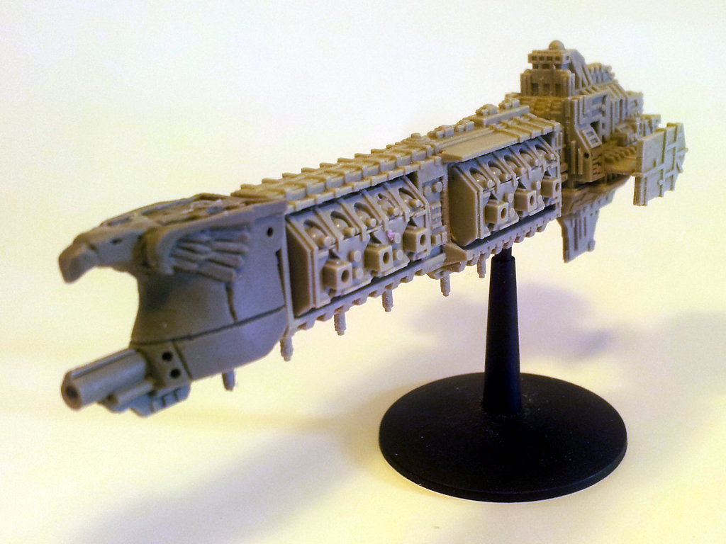
As discussed on the RA Forum I decided that I wanted to bulk out the torso silhouette a bit by adding some close in defence weapons. The weapon of choice was a gatling cannon so I put a design together. The intention was to have one on each side, limiting the design as I had to make it easily mirror-able (so that I didn’t have to scratchbuild two complete separate guns).
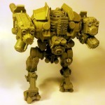
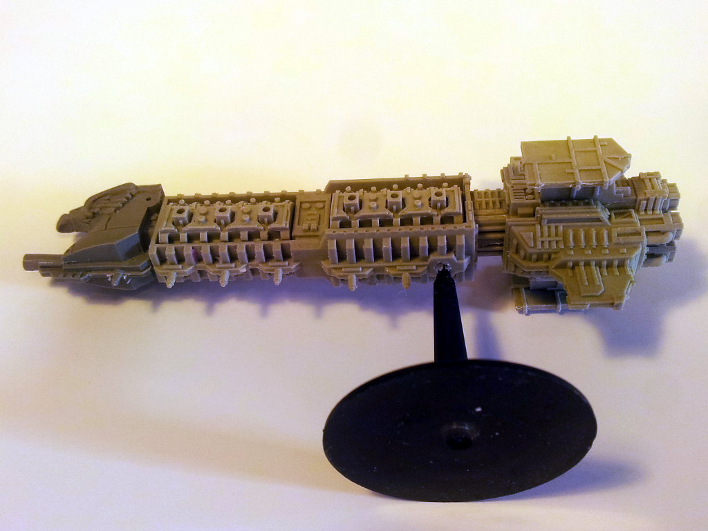
This is what I ended up with:
The problem was that I wasn’t 100% happy with it. The gatling cannon design was OK and could do with some durther detailing/refinement. My main concern was that everything was just looking far too symmetrical: the mirrored main cannons and now the close in defence weapons. I felt that it made for quite a boring design, so the decision was made to ditch one of them in favour of something else. This was particularly annoying since I’d already made design compromises to make the gatling cannon easily mirror-able and I’d already made gatling cannon moulds for both sides!
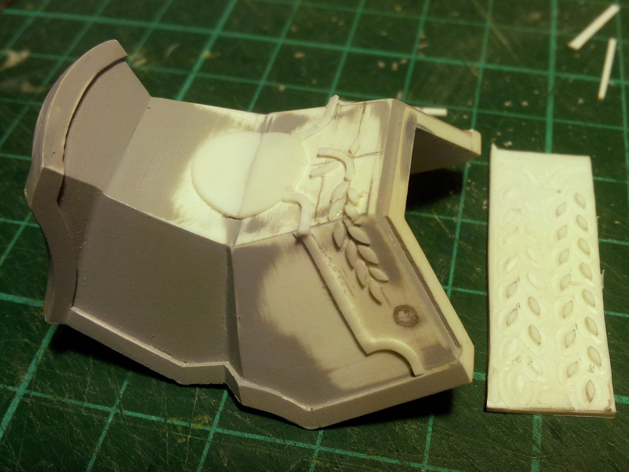
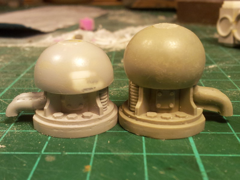
I threw around several ideas for the “something else” before settling on something I liked. Initially my mate Seb suggested smoke launchers, but I didn’t like the aesthetic of the standard tank mounted smoke launcher. I toyed with the idea of a sensor pod and then just a plain armour plate (of which I even made a mock-up in styrene) but ultimately decided to return to some kind of smoke/chaff launching system. I was inspired by some photos I took aboard the US Amphibious Assault Vessel “Bonhomme Richard” as the guest of Battlefleet Gothic “royalty” Nate Montes last year and the countermeasures launcher pods mounted on the side of naval aircraft.
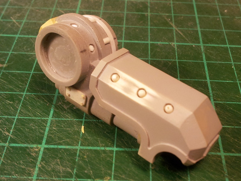
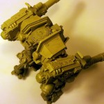
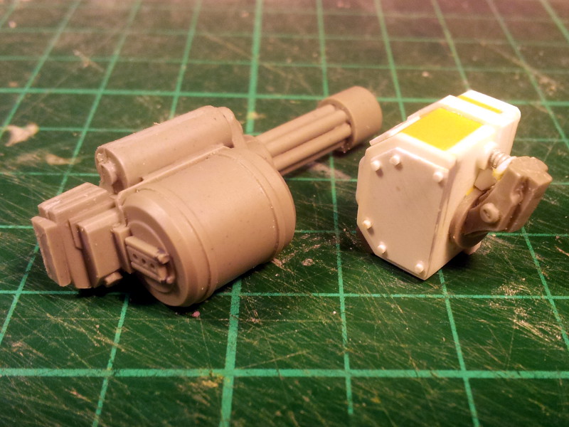
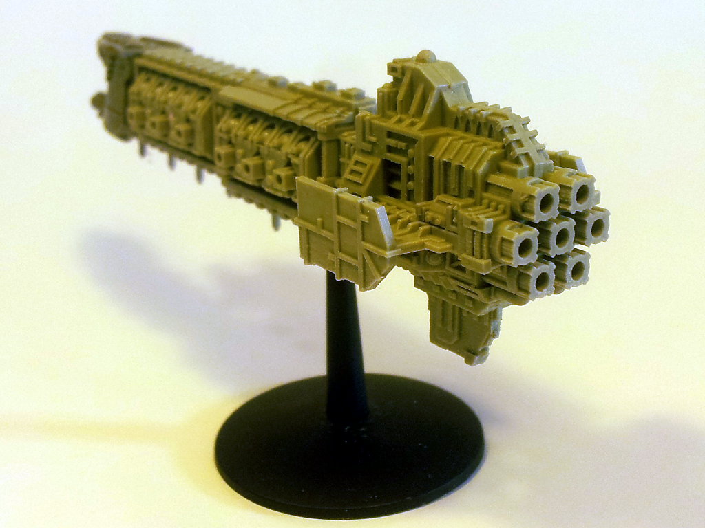
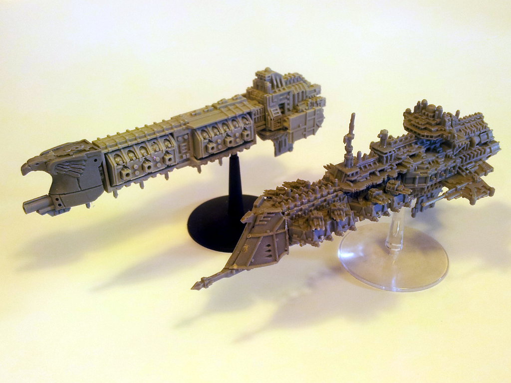
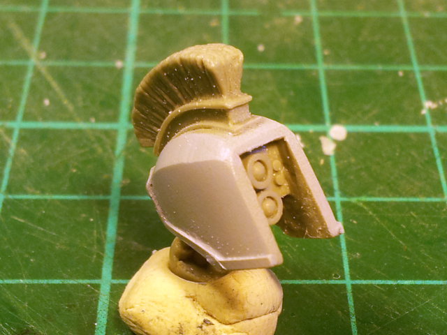
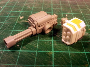
Here’s what I came up with: the galting cannon and smoke launcher. I realise the smoke launcher looks similar to a missile pod – they have very similar functions so it’s not surprising. Hell somebody can claim it is a missile pod on their model if they want!

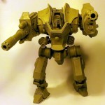
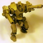
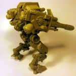
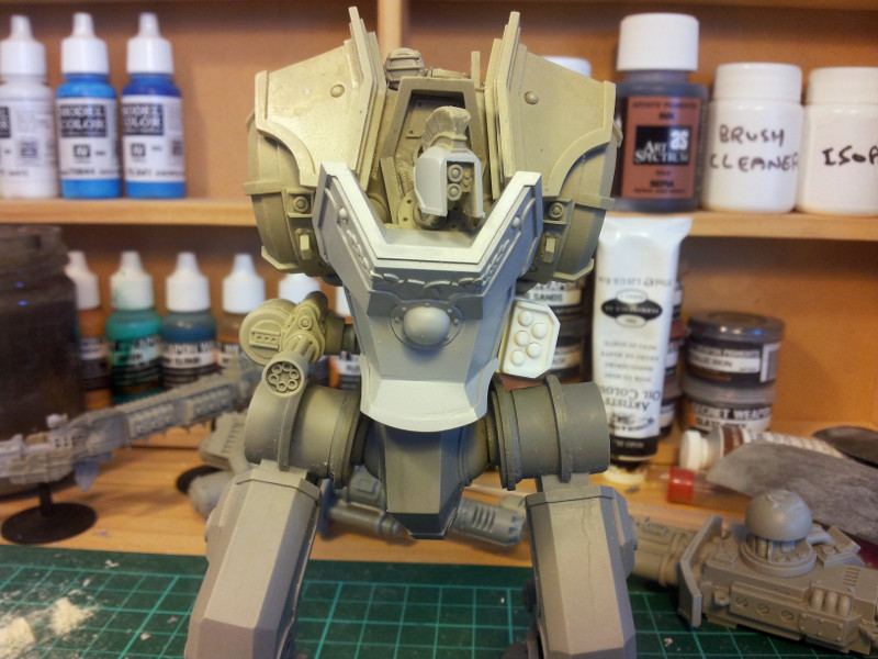
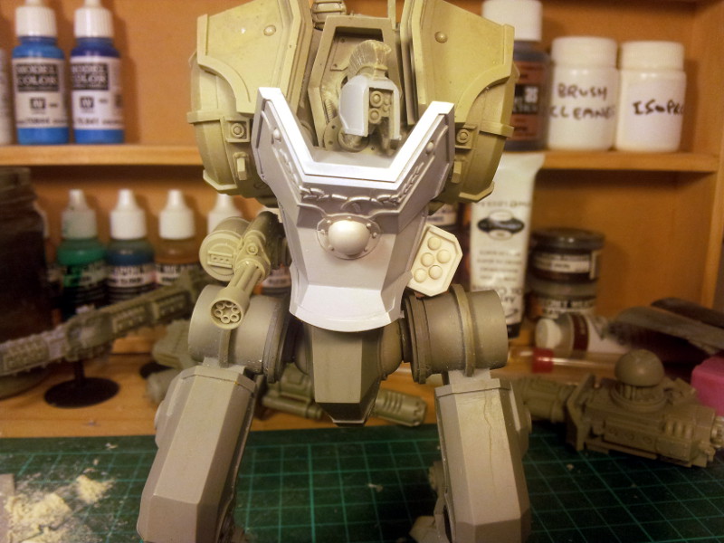
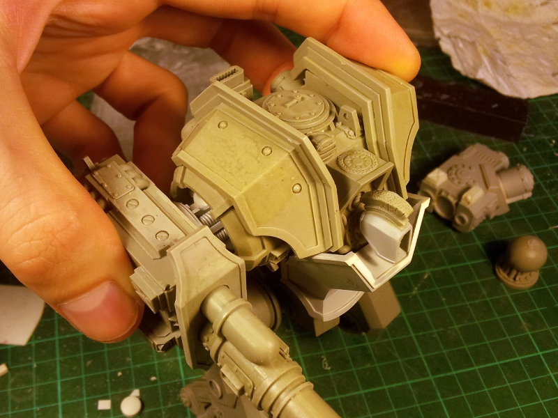
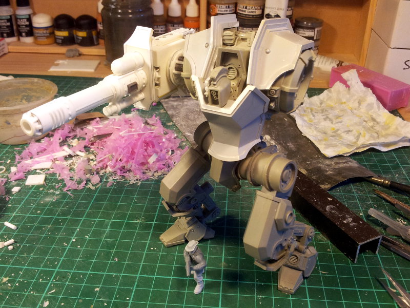
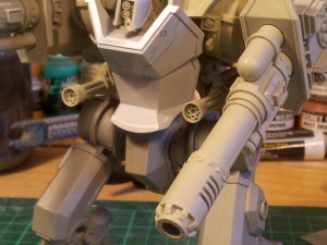
And here’s how they look on the model:
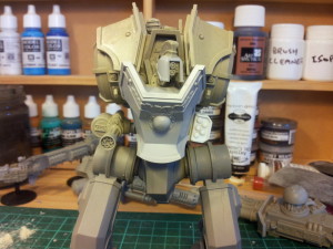
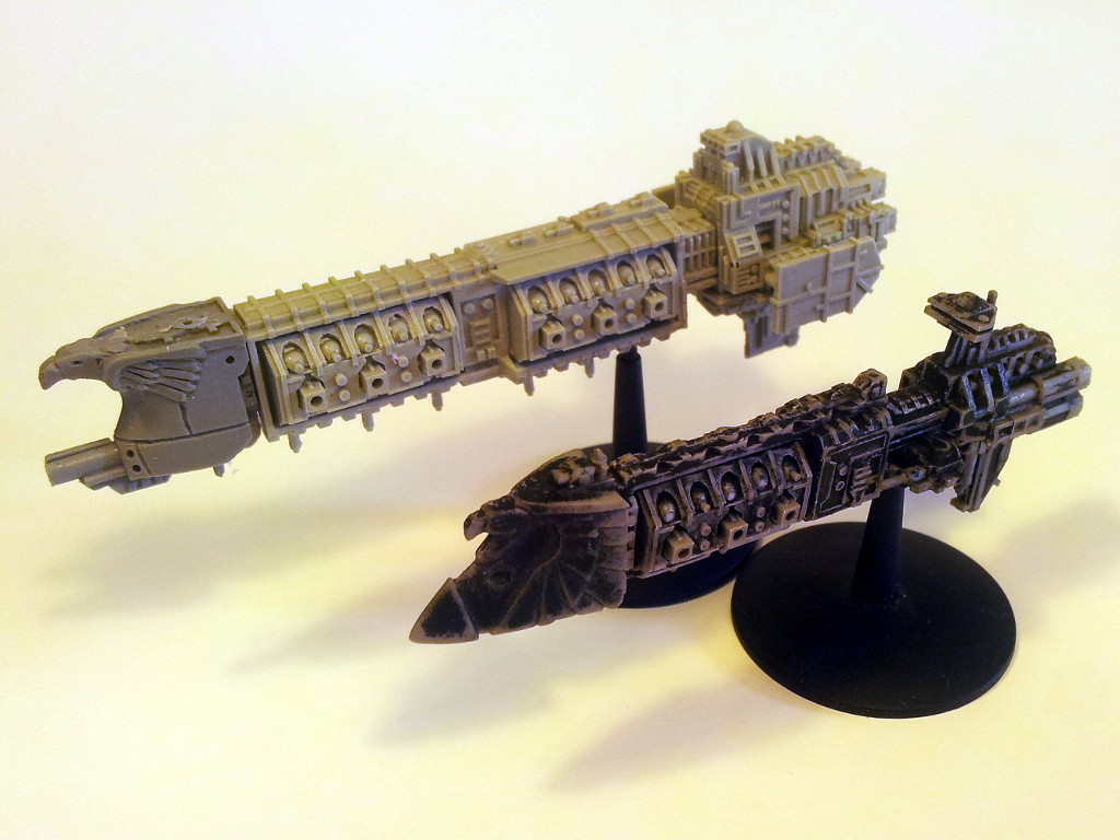
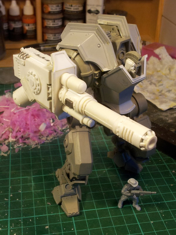
There is another problem though: the gatling cannon sits out too far. This was a limitation of the mirror-able design and another thing I was never happy with. To prove the point I grabbed a tertiary cast of the cannon, hacked back the mounting socket and drilled a new one into the side of the cannon body. This brings the cannon in much closer to the torso and I think it looks far better:
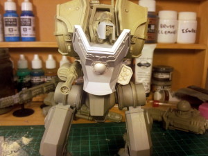
Subtle, sure, but it’s just one of those things I need to do to be happy with it. OF coure, that was only a demonstration and I now have to do it for real. After some deliberation I decided to hack up the original gatling cannon master parts. They have no other use and I can always cast more from the now redundant moulds if need be. Plus I’ll take the opportunity to update the gatling cannon a bit more: it really needs another detailing pass!
I have a deadline of 3 weeks to get this finished and some samples cast – let’s see if I can manage it! Nothing spurs productivity like a deadline 😉